Linggo, Oktubre 12, 2014

Week 12: Maximum Power Transfer

Maximum Power Transfer

What is Maximum Power Transfer?
-In electrical engineering, the maximum power transfer theorem states that, to obtain maximum external power from a source with a finite internal resistance, the resistance of the load must equal the resistance of the source as viewed from its output terminals. Moritz von Jacobi published the maximum power (transfer) theorem around 1840; it is also referred to as "Jacobi's law".

The theorem results in maximum power transfer, and not maximum efficiency. If the resistance of the load is made larger than the resistance of the source, then efficiency is higher, since a higher percentage of the source power is transferred to the load, but the magnitude of the load power is lower since the total circuit resistance goes up.
If the load resistance is smaller than the source resistance, then most of the power ends up being dissipated in the source, and although the total power dissipated is higher, due to a lower total resistance, it turns out that the amount dissipated in the load is reduced.
The theorem states how to choose (so as to maximize power transfer) the load resistance, once the source resistance is given. It is a common misconception to apply the theorem in the opposite scenario. It does not say how to choose the source resistance for a given load resistance. In fact, the source resistance that maximizes power transfer is always zero, regardless of the value of the load resistance.

Procedures in applying Maximum Power Transfer:
·        * Apply Thevenin’s Theorem on a circuit
·        *  Solve for VTh and RTh

·        * Apply the power delivered to the load resistance (RL) and RL = RTh, The formula for power delivered to RL is:

* To find the maximum power, differentiate the above expression with respect to resistance RL and equate it to zero. Thus,
Thus in this case, the maximum power will be transferred to the load when load resistance is just equal to internal resistance of the battery.

Example:
Find the power dissipated by the 0.8Ω resistor.  
With this value of load resistance, the dissipated power will be 39.2 watts:
If we were to try a lower value for the load resistance (0.5 Ω instead of 0.8 Ω, for example), our power dissipated by the load resistance would decrease:
Power dissipation increased for both the Thevenin resistance and the total circuit, but it decreased for the load resistor. Likewise, if we increase the load resistance (1.1 Ω instead of 0.8 Ω, for example), power dissipation will also be less than it was at 0.8 Ω exactly:

Reflection:
The Maximum Power Transfer Theorem is not so much a means of analysis as it is an aid to system design. Simply stated, the maximum amount of power will be dissipated by a load resistance when that load resistance is equal to the Thevenin/Norton resistance of the network supplying the power. In solving for problems like these, It is very important that we have a correct Thevenin/Norton equivalent circuit because if Vth and Rth is wrong, then the power dissipated by the load resistance (RL) will also be wrong.

Video(s):
Video that will explain more about the derivation in the procedure


Maximum Power Transfer

“Every idea is in the soul of its owner. No other power can shift it to another soul, that is why we have the telephone, aircraft, etc, each having its unique inventor.”
― Michael Bassey Johnson

Week 11: Thevenin's Theorem with Dependent Sources

Thevenin's Theorem with Dependent Sources

Cases in Thevenin's Theorem:

■ CASE 1: If the network has no dependent sources, we turn off all independent sources. RTH is the input resistance of the network looking between terminals A and B. 

■ CASE 2: If the network has dependent sources, we turn off all independent sources. As with superposition, dependent sources are not to be turned off because they are controlled by circuit variables. We apply a voltage source at terminals A and B and determine the resulting current Io. Then, RTH = Vo/Io . Alternatively, we may insert a current source Io at terminals A-B and find the terminal voltage Vo. Again RTH = Vo/Io. Either of the two approaches will give the same result. In either approach we may assume any value of and Vo and Io. For example, we may use Vo = 1V or Io = 1A or even use unspecified values of Vo or Io.

It often occurs that RTH takes a negative value. In this case, the negative resistance (V = -iR) implies that the circuit is supplying power. This is possible in a circuit with dependent sources.

Thevenin’s theorem is very important in circuit analysis. It helps simplify a circuit. A large circuit may be replaced by a single independent voltage source and a single resistor. This replacement technique is a powerful tool in circuit design.


As mentioned earlier, a linear circuit with a variable load can be replaced by the Thevenin equivalent, exclusive of the load. The equivalent network behaves the same way externally as the original circuit. Consider a linear circuit terminated by a load RL, . The current IL through the load and the voltage VL across the load are easily determined once the Thevenin equivalent of the circuit at the load’s terminals is obtained.

Suppose that R1 =5Ω , R2 =3Ω and IS =2A .
Solution
The circuit has both independent and dependent sources. In these cases, we need to find the open circuit voltage to determine the Thevenin Equivalent Circuit

Open Circuit Voltage

Open circuit voltage means the voltage across the terminals of the network without connecting any extra element or connection:
Since there is no connection, the current of R2 is zero. To solve the circuit lets write KVL for the left hand side loop assuming IR1 defined from left to right:
+Vx+R1×IR1+Vx=0
→2Vx=−R1×IR1
→Vx=−R1×IR12
But what is IR1? R1 is in series with the current source; they have only one node shared and there is no other element connected there. This means that all current of IS must pass through R1 . Therefore, IR1=IS=2A .
If we apply this to the equation above, we have
Vx=−R1×IR12→Vx=−5V.
Since no current passing through R2 we can easily see that VOC=Vx . If it is not clear, you could find this by applying KVL to the right hand side loop:
−Vx+R2×IR2+VOC=0
→−Vx+R2×0+VOC=0
→VOC=Vx=−5V

Calculating RTH
The only thing left is to calculate RTh which can be easily found by
R­TH=VOC / ISC=−5−53=3Ω
Thevenin's Equivalent Network
VTh=VOC=−5V
RTh=3Ω 

Reflection/Learnings:
This week, We discussed about Thevenin's Theorem with Dependent Sources. I didnt include this in the previous section because I wanted to explain it in more detail. Actually, In Thevenin's Theorem, There were two cases. Case 1 are for circuits that doesn't have any dependent sources while Case 2 are for circuits that contains at least one dependent source. To solve for problems with dependent sources, We first turn off all independent sources by replacing all voltage sources as a closed branch and replacing all current sources with an open branch. Dependent sources cannot be turned off because they are controlled by circuit variables and then we simply remove one load in a circuit and instead of replacing it with an open circuit and measuring the open circuit voltage, We add an additional voltage or current source. The values of the added sources completely depends on you. You can assume any value for it as long as it is not 0. 

Video(s):
Thevenin's Theorem with Dependent Source
Thevenin's Theorem with one Dependent Source 

Electricity is often called wonderful, beautiful; but it is so only in common with the other forces of nature. The beauty of electricity or of any other force is not that the power is mysterious, and unexpected, touching every sense at unawares in turn, but that it is under law, and that the taught intellect can even govern it largely. The human mind is placed above, and not beneath it, and it is in such a point of view that the mental education afforded by science is rendered super-eminent in dignity, in practical application and utility; for by enabling the mind to apply the natural power through law, it conveys the gifts of God to man.
--Michael Faraday

Week 10: Thevenin and Norton's Theorem

Thevenin's Theorem

What is Thevenin's Theorem?

-Thevenin's Theorem states that it is possible to simplify any linear circuit, no matter how complex, to an equivalent circuit with just a single voltage source and series resistance connected to a load. The qualification of “linear” is identical to that found in the Superposition Theorem, where all the underlying equations must be linear (no exponents or roots). If we're dealing with passive components (such as resistors, and later, inductors and capacitors), this is true. However, there are some components (especially certain gas-discharge and semiconductor components) which are nonlinear: that is, their opposition to current changes with voltage and/or current. As such, we would call circuits containing these types of components, nonlinear circuits.


Thevenin's Theorem is especially useful in analyzing power systems and other circuits where one particular resistor in the circuit (called the “load” resistor) is subject to change, and re-calculation of the circuit is necessary with each trial value of load resistance, to determine voltage across it and current through it.

Simple Steps to Analyze Electric Circuit through Thevenin’s theorem.

* Open the load resistor
* Calculate / measure the Open Circuit Voltage. This is the Thevenin Voltage (VTH)
* Open Current Sources and Short Voltage Sources.
* Calculate /measure the Open Circuit Resistance. This is the Thevenin Resistance (RTH)
* Now, Redraw the circuit with measured open circuit Voltage (VTH) in Step (2) as voltage Source and measured open circuit resistance (RTH) in step (4) as a series resistance and connect the load resistor which we had removed in Step (1). This is the Equivalent Thevenin Circuit of that Linear Electric Network or Complex circuit which had to be simplified and analyzed. You have done.
* Now find the Total current flowing through Load resistor by using the Ohm’s Law IT = VTH/ (RTH + RL)

Example:
Find VTH, RTHand the load current flowing through and load voltage across the load resistor in fig (1) by using Thevenin’s Theorem.
Solution:
* Step 1
Open the 5kΩ load resistor (Fig 2)


Step 2
Calculate / measure the Open Circuit Voltage. This is the Thevenin Voltage (VTH). Fig (3)
We have already removed the load resistor from figure 1, so the circuit became an open circuit as shown in fig 2. Now we have to calculate the Thevenin’s Voltage. Since 3mA Current flows in both 12kΩ and 4kΩ resistors as this is a series circuit because current will not flow in the 8kΩ resistor as it is open.
So 12V (3mA  x 4kΩ) will appear across the 4kΩ resistor. We also know that current is not flowing through the 8kΩ resistor as it is open circuit, but the 8kΩ resistor is in parallel with 4k resistor. So the same voltage (i.e. 12V) will appear across the 8kΩ resistor as 4kΩ resistor. Therefore 12V will appear across the AB terminals. So,
VTH = 12V 
Step 3
Open Current Sources and Short Voltage Sources. Fig (4)
Step 4
Calculate /measure the Open Circuit Resistance. This is the Thevenin Resistance (RTH)
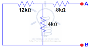
We have Reduced the 48V DC source to zero is equivalent to replace it with a short in step (3), as shown in figure ()  We can see that 8kΩ resistor is in series with a parallel connection of 4kΩ resistor and  12k Ω resistor. i.e.:
8kΩ + (4k Ω || 12kΩ) ….. (|| = in parallel with)
RTH = 8kΩ + [(4kΩ x 12kΩ) / (4kΩ + 12kΩ)]
RTH = 8kΩ + 3kΩ
RTH = 11kΩ
Step 5
Connect the RTHin series with Voltage Source VTH and re-connect the load resistor. This is shown in fig (6) i.e. Thevenin circuit with load resistor.
Step 6
Now apply the last step i.e. calculate the total load current & load voltage as shown in fig 6.
IL = VTH/ (RTH + RL)
= 12V / (11kΩ + 5kΩ) → = 12/16kΩ
IL= 0.75mA
And
VL = ILx RL
VL = 0.75mA x 5kΩ
VL= 3.75V

Norton's Theorem
What is Norton's Theorem?

-Norton's Theorem states that it is possible to simplify any linear circuit, no matter how complex, to an equivalent circuit with just a single current source and parallel resistance connected to a load. Just as with Thevenin's Theorem, the qualification of “linear” is identical to that found in the Superposition Theorem: all underlying equations must be linear (no exponents or roots).
Contrasting our original example circuit against the Norton equivalent: it looks something like this:

. . . after Norton conversion . . .
Steps to follow for Norton's Theorem:
  • (1) Find the Norton source current by removing the load resistor from the original circuit and calculating current through a short (wire) jumping across the open connection points where the load resistor used to be.
  • (2) Find the Norton resistance by removing all power sources in the original circuit (voltage sources shorted and current sources open) and calculating total resistance between the open connection points.
  • (3) Draw the Norton equivalent circuit, with the Norton current source in parallel with the Norton resistance. The load resistor re-attaches between the two open points of the equivalent circuit.
  • (4) Analyze voltage and current for the load resistor following the rules for parallel circuits.

Reflection/Learnings:

Thevenin's Theorem pretty much  simplifies an entire circuit no matter how complex into an equivalent circuit with only one Voltage source (Vth). In Thevenin's theorem, We also change one resistor into an open circuit.  It does this because we need to measure the open circuit voltage of the circuit. In Norton's theorem the same concept is pretty much applied but instead of turning one load into an open circuit and measuring the open circuit voltage, We turn it into a short circuit and then we measure the short circuit current. In this section however, I have only discussed the case 1 of Thevenin's Equivalent and in the next section, I will discuss the case 2 of Thevenin's Equivalent as well as explain both cases.

Video:
Introduction to Thevenin's Theorem
Introduction to Norton's Theorem

Engineering problems are under-defined, there are many solutions, good, bad and indifferent. The art is to arrive at a good solution. This is a creative activity, involving imagination, intuition and deliberate choice.
--Ove Arup

Lunes, Agosto 25, 2014

Week 9: Superposition

Superposition

What is Superposition?

- Superposition is another algorithmic circuit analysis method, with a prescribed procedure, like the node-voltage or loop-current methods.

It applies only in circuits with 2 or more independent sources.
It comes from the mathematical notion of superposition in which a final solution can be built as the sum of two or more partial solutions. It works well when the partial solutions can be obtained very easily. (Using voltage dividers or resistor reduction techniques.)

Superposition only applies to linear circuits, which are made up of linear circuit elements: resistors, voltage and current sources, capacitors, inductors, and linear amplifiers. It does not apply when the circuit has non-linear elements like diodes and transistors (electronics).

The Superposition Procedure:

Here are the steps: (Recall that the method only applies to circuits with two or more independent sources.)

1. Make a partial circuit by choosing one source to keep and turning of all of the other independent sources.
 -To “turn off” a voltage source, we turn it into a short circuit (zero volts and carries any amount of current.) To turn off a current source, we convert it to an open circuit (zero amps and any amount of voltage across it.)
2. Solve this “partial circuit” for the quantities of interest. Use whatever techniques that are applicable to the partial circuit: resistor reductions, voltage dividers, source transformations, or even node voltage.
3. Go back to the original circuit and create another partial circuit by choosing another source to keep (different than the first one) and turning off all of the other sources in the circuit.
4. Solve the second partial circuit for the quantities of interest.
5. Repeat the process until each independent source has been used in a partial circuit.
6. Sum up the all of the partial results to get the total results for the quantities of interest.
 -If there are n independent sources in a circuit, then when using superposition, you would expect to solve n partial circuits and find n partial results for whatever you are looking for.

Example:
4Ω and 2Ω are in series and also 3Ω and 1Ω :
Now 4Ω and 6Ω are parallel:
4Ω||6Ω=4×6/4+6=2.4Ω
So using Ohm's law:
Ix1=5V/2.4Ω=2.083A


For a moment forget Ix and concentrate on finding current of resistors. If we have the current of resistors, we can easily apply KCL and find Ix2 . So, 4Ω and 2Ω are parallel and also 3Ω and 1Ω are parallel:
4Ω||2Ω=4×2/4+2=43Ω
3Ω||1Ω=3×1/3+1=34Ω

Now, we can find their voltage drops:
V4Ω||2Ω=4/3×−3A=−4V
V3Ω||1Ω=3/4×−3A=−2.25V

Please note that the voltage drop on 4Ω||2Ω is the same as 4Ω and 2Ω voltage drops, because the circuits are equivalent and all are connected to the same nodes. The same statement is correct for 3Ω||1Ω voltage drop and 3Ω and 1Ω voltage drops. So

V4Ω=V2Ω=V4Ω||2Ω=−4V
V3Ω=V1Ω=V3Ω||1Ω=−2.25V

To find Ix2 all we need is to write KCL at one of the nodes:
−I2Ω+Ix2+I3Ω=0
→Ix2=I2Ω−I3Ω 

I2Ω and I3Ω can be found using Ohm's law:
I2Ω=V2Ω2Ω=−42=−2V
I3Ω=V3Ω3Ω=−2.253=−0.75V

Therefore,
Ix2=−1.25A

And
Ix=Ix1+Ix2=2.083−1.25=0.8333A
Ix=0.8333A

Reflection:
Superpositon overall is a topic with an easy-to grasp concept. To solve a circuit using the superposition theorem, We need to choose one source and then we need to turn off the other sources. The choosing of the sources is the most crucial part because choosing the wrong source to turn on might lead to a wrong output. After that, its only a matter of applying the basic circuit laws and equations to solve the problem.

Video:
Superposition

Superposition problem with dependent source

Thanks for visiting my Blog!!. The tenth post wont be arriving for a while. See ya!!!

I find that the harder I work, the more luck I seem to have.

-Thomas Jefferson

Lunes, Agosto 18, 2014

Week 8: Linearity Property and Source Transformation

Linearity Property

What is Linearity Property?
-Linear property is the linear relationship between cause and effect of an element. This property gives linear and nonlinear circuit definition. The property can be applied in various circuit elements. The homogeneity (scaling) property and the additivity property are both the combination of linearity property.

The homogeneity property is that if the input is multiplied by a constant k then the output is also multiplied by the constant k. Input is called excitation and output is called response here. As an example if we consider ohm’s law. Here the law relates the input i to the output v.

Mathematically,                 v= iR

If we multiply the input current  i by a constant k then the output voltage also increases correspondingly by the constant k. The equation stands,      
                                     kiR = kv

The additivity property is that the response to a sum of inputs is the sum of the responses to each input applied separately.

Using voltage-current relationship of a resistor if

                                       v1 = i1R       
and  
                                       v2 = i2R
 Applying (i1 + i2)gives
 V = (i1 + i2)R = i1R+ i2R = v1 + v2

We can say that a resistor is a linear element. Because the voltage-current relationship satisfies both the additivity and the homogeneity properties.

What is linear circuit?
 -A circuit is linear if the output is linearly related with its input.

Example of a Linear Circuit:

See a circuit in figure 1. The box in the circuit is a linear circuit. We cannot see any independent source inside the linear circuit.

Source Transformation

What is Source Transformation?

-Independent current sources can be turned into independent voltage sources, and vice-versa, by methods called "Source Transformations." These transformations are useful for solving circuits. We will explain the two most important source transformations, Thevenin's Source, and Norton's Source, and we will explain how to use these conceptual tools for solving circuits.

For more info about Thevenin's Source, Click here.
For more info about Norton's Source, Click here.

Conversion of Voltage Source to Current Source

To convert a Voltage Source into a current one, We need to follow these steps:

1. Make short circuit between two terminals A and B as we done in figure. Find the short circuit current and let it be I.
2. Measure the resistance at the terminals with load removed and sources of e.m.f s replaced by their internal resistances if any. Let the resistance is R.
3. Then equivalent current source can be represented by a single current source of magnitude I in parallel with resistance R.

Example:

Conversion of Current Source to Voltage Source

To do this, We have to do the same inverse procedure.

Example:


Reflection:
This week, I learned that converting sources is actually very easy. To covert a voltage source into a current one, We simply change the position of the resistors from series to parallel. To convert a current source into a voltage one, We change the position of the resistors from parallel to series. But before we apply source transformation, We must analyze the problem and identify the position of the resistors first. If the source is a voltage one and if the resistor connected to the source is in a parallel connection, then source transformation is not applicable. If the source is a current one and if the resistor connected to the source is in a series connection, then source transformation is also not applicable.

Videos:
Linearity Property:

Source Transformation:

Circuit of Life:

Thanks for visiting my Blog!!. The ninth post will be arriving next week. See ya!!

Linggo, Agosto 10, 2014

Week 7: Mesh Analysis

Mesh Analysis

What is Mesh Analysis?
-Mesh analysis or the Mesh Current Method, also known as the Loop Current Method, is quite similar to the Branch Current method in that it uses simultaneous equations, Kirchhoff's Voltage Law, and Ohm's Law to determine unknown currents in a network. It differs from the Branch Current method in that it does not use Kirchhoff's Current Law, and it is usually able to solve a circuit with less unknown variables and less simultaneous equations, which is especially nice if you're forced to solve without a calculator.

What is a "Mesh"?
-Basically, A mesh is a loop that does not have any loops in it.


In the figure above, the following meshes are: B1-R1-R2-B1, and B2-R3-R2-B2 but B1-R1-R3-B2-B1 is not a mesh because it contains other loops in it.

Mesh Analysis without Current Sources

Steps:
1. Identify loops within the circuit encompassing all components.
2. Assign mesh currents to the number of meshes found in the circuit.
3. Apply current directions to each of the mesh currents in the circuit. The choice of each current's direction is entirely arbitrary. If the assumed direction is wrong, the answer for that current will be a negative answer.
4. Apply Kirchoff's Voltage Law (KVL) to each of the meshes.
5. Use Ohm's Law to express the voltages in terms of mesh currents.
6. Solve the resulting n simultaneous equations to get the mesh currents.

Mesh Analysis with Current Sources

Two cases to consider:
Case 1: A current source exists only in one mesh.
Case 2: A current source exists between two meshes.

What is a Supermesh?
 - A supermesh occurs when a current source is contained between two essential meshes. The circuit is first treated as if the current source is not there. This leads to one equation that incorporates two mesh currents. Once this equation is formed, an equation is needed that relates the two mesh currents with the current source. This will be an equation where the current source is equal to one of the mesh currents minus the other. The following is an example of a supermesh.


Reflection:
This week, I learned that meshes in a circuit are loops that does not have any loops in them and that they require Mesh Analysis to be solved. Mesh Analysis or Mesh Current Method are almost similar in Branch Current method because the way to solve them are both exactly the same except that mesh analysis requires KVL while nodal analysis requires KCL. Both methods of circuit analysis are very useful in solving all types of circuit problems. Overall, I learned that mesh analysis is much easier than the Branch current method because unlike in the Branch current method, We don't need any reference components or parts like the reference nodes in the Branch current method.

Videos:
Mesh Analysis Introduction:

Mesh Analysis with Independent current sources:

Mesh and Supermesh:

Thanks for visiting my Blog!!! The eight post will be arriving next week. See ya!!!

“The best teachers are those that can influence even the poorest of all learners.”
― Kim Panti

Linggo, Agosto 3, 2014

Week 6: Wye-Delta Transformations

Wye-Delta Transformations

What is  Y-Δ transformation? 
- The Y-Δ transform, also written wye-delta and also known by many other names, is a mathematical technique to simplify the analysis of an electrical network. The name derives from the shapes of the circuit diagrams, which look respectively like the letter Y and the Greek capital letter Δ. This circuit transformation theory was published by Arthur Edwin Kennelly in 1899. It is widely used in analysis of three-phase electric power circuits.

- The Y-Δ transform is known by a variety of other names, mostly based upon the two shapes involved, listed in either order. The Y, spelled out as wye, can also be called T or star; the Δ, spelled out as delta, can also be called triangle, Π (spelled out as pi), or mesh. Thus, common names for the transformation include wye-delta or delta-wye, star-delta, star-mesh, or T-Π.

Illustration of the transformation in its T-Π representation

Formulas:

Equations for the transformation from Δ-load to Y-load:


Equations for the transformation from Y-load to Δ-load:


Δ and Y circuits with the labels which are used in this article.

Reflection:

This week, I learned that the transformation is used to establish equivalence for networks with three terminals. Where three elements terminate at a common node and none are sources, the node is eliminated by transforming the impedances. For equivalence, the impedance between any pair of terminals must be the same for both networks. The equations given here are valid for complex as well as real impedances. I also learned that this topic is one of the easiest topic we have ever tackled in our Circuit Class because it only uses a specific formula unlike other topics.

Video:

Wye-Delta Transformation:

Delta-Wye Transformation:

Thanks for visiting my Blog!! The seventh post will be arriving next week. See ya!!

“Many of life's failures are people who did not realize how close they were to success when they gave up.”


-Thomas A. Edison