First-Order Circuits
What are First-Order Circuits?
First order circuits are circuits that contain only one
energy storage element (capacitor or inductor), and that can, therefore, be
described using only a first order differential equation. The two possible
types of first-order circuits are:
- RC
(resistor and capacitor)
- RL
(resistor and inductor)
RL and RC circuits is a term we will be using to describe a
circuit that has either a) resistors and inductors (RL), or b) resistors and
capacitors (RC).
(A).
An RL Parallel Circuit:
An RL Circuit has at least one resistor (R) and one inductor
(L). These can be arranged in parallel, or in series. Inductors are best solved
by considering the current flowing through the inductor. Therefore, we will
combine the resistive element and the source into a Norton Source Circuit. The
Inductor then, will be the external load to the circuit. We remember the
equation for the inductor:
V(t) = L(di/dt)
If we apply KCL on the node that forms the positive terminal
of the voltage source, we can solve to get the following differential equation:
Isource(t) = Ldiinductor(t)/Rndt
+ Iinductor(t)
The "Source-Free" RL Circuit:
If we take our previous circuit, wait for a while for the
current to level off, and then open the switch so the battery is no longer in
the circuit, what happens. If the circuit had just a resistor the current would
drop immediately to zero. With the inductor the change in current means a
change in magnetic flux so the inductor opposes the change. The current does
eventually reach zero but it takes some time to get there.
To see why, apply Kirchoff's loop rule. With the switch
opened we have:
IR + L dI/dt = 0
or dI/dt = -IR/L
Solving this for current gives I(t) = Io e-t/t
The potential difference across the resistor has a similar
form:
DVR = e e-t/t
The potential difference across the inductor is negative
because it's acting like a battery hooked up in the opposite direction:
DVL = -e e-t/t
Once again, the graph of current as a function of time in
the RL circuit has the same form as the graph of the capacitor voltage as a
function of time in the discharging RC circuit, while the graph of the inductor
voltage as a function of time in the RL circuit has the same form as the graph
of current vs. time in the discharging RC circuit.
Graph:
(B).
An RC Parallel Circuit:
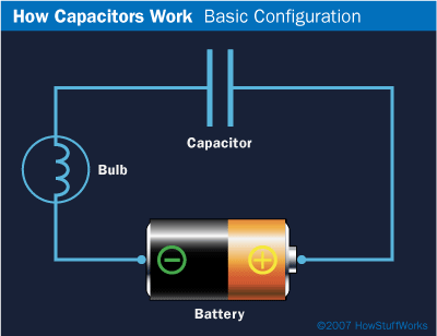
An RC circuit is a circuit that has both a resistor (R) and
a capacitor (C). Like the RL Circuit, we will combine the resistor and the
source on one side of the circuit, and combine them into a thevenin source.
Then if we apply KVL around the resulting loop, we get the following equation:
Vsource = RC( dvcapacitor(t)/dt) + Vcapacitor
(t)
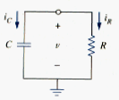
The "Source-Free" RC Circuit
When applied,
dVC/dt + dVR/dt = 0,
where VC is the voltage drop across the
capacitor and VR is the voltage drop across the resistor.
The change in the voltage drop across the capacitor is given
by our previous expression,
dVC/dt = 1/C
The change in the voltage drop across the resistor can be
obtained from Ohm's law
VR=RI=dVR/dt=Rdi/dt
Substituting these changes in voltage into Kirchoff's
equation gives
1/C + Rdi/dt = 0,
where the current due to the flow of charge on or off the
capacitor is the same as through the resistor.
Now we need some initial conditions. Notice that although
the capacitor behaves as an open circuit to DC, current must flow to charge or
discharge the capacitor. Lets take the case where the capacitor is initially
charged and then the circuit is closed and the charge is allowed to drain off
the capacitor (eg. closing a switch). The resulting current will flow through
the resistor.
Solving for the current we obtain
I(t) = I0e t/RC
where V(T=0) = VO is the initial
voltage across the capacitor and t=RC is the commonly defined time
constant of the decay. You should also be able to solve for the voltage across
the capacitor and charge on the capacitor.
For the case of an applying voltage VR being
suddenly placed into the circuit (inserting a battery) the capacitor is
initially not charged and the voltage across the capacitor is
Graph:
Reflection:
There are two types of First-Order Circuits, These are the Resistor-Inductor circuits or RL and the Resistor-Capacitor circuits or RC. First-Order circuits are characterized by a First-Order differential equation. There are also "Source-Free" RL and RC circuits. The sources in these circuits are usually separated from a switch and when the switch is turned on, the switch will supply power to the capacitor or inductor and when the switch is turned off, there is still power in the circuit because the capacitor and inductors absored energy from the source.
Video(s):
RL Circuit
RC Circuit
Source-Free RC circuits
When you look at the inner workings of electrical things,
you see wires. Until the current passes through them, there will be no light.
That wire is you and me. The current is God. We have the power to let the
current pass through us, use us, to produce the light of the world, Jesus, in
us. Or we can refuse to be used and allow darkness to spread.


.png)

.jpg)


.png)


.png)


